CERN Accelerating science

This website is no longer maintained. Its content may be obsolete. Please visit http://home.cern/ for current CERN information.

CERN Accelerating science

Installation of the TDIS unit for the High-Luminosity LHC

Nearly one year after the start of the assembly activities the first 3-module-device Target Dump Injection Segmented (TDIS) unit is ready to be installed. This time span has allowed the project team to troubleshoot and ultimately validate the equipment assembly procedure and its overall design.

One major milestone achieved during this process was the completion of an irradiation experiment at CERN’s HiRadMat facility in 2018. A complete prototype TDIS module was exposed to several high-intensity proton beam pulses, reproducing in its core (two movable assemblies named jaws) the thermomechanical response expected by HL-LHC beam impacts. As anticipated/expected by previous simulations , the jaw assembly, made up mainly of isostatic graphite absorbing blocks supported by an advanced Titanium-Zirconium-Molybdenum (TZM) stiffener, did not show any beam-induced degradation, which was corroborated by online instrumentation and post-irradiation examinations. The      outstanding strength at high temperatures along with the remarkable thermal conductivity plus an average specific heat make the TZM the most suitable material to cope with the challenging energy level at the TDIS back-stiffener’s spot. That is why it was chosen over many other candidates such as Glidcop® (used in back-stiffeners of most LHC collimators).

The on-line monitoring of the HiRadMat module also provided an insight into the performance of the built-in cooling system, which was able to cool the jaws down to room temperature within about 10-15 minutes after beam shots (when TZM’s temperature exceeded 200°C). The cooling system was subject of another test aiming at evaluating its capacity to keep the jaw temperature below 50°C while beams are being injected into the HL-LHC. During LHC filling, continuous resistive-wall heating of the TDIS jaws is present, mostly on surfaces directly exposed to particle beams. The testing set-up included four 1000-watt lamps to get the jaws heated up in a manner similar to real-time operation.

Further validation tests were conducted on another essential system of the injection absorber: a complex mechanism containing almost 500 components denominated “mechanical table”, responsible of the 0.01 mm-accurate motion of the jaws inside the vacuum chamber. Two mechanical tables endured, without any hint of fatigue/deteriotation, 15000 full-stroke cycles, pessimistically emulating the expected displacements over the TDIS’s lifetime. Moreover, prior to running the mechanical table cycling test, the lubricated lead screws (by far the most sensitive components of this sub-assembly) were gamma irradiated up to 5 MGy, several factors higher compared to the calculated cumulated dose at the TDIS location in the LHC tunnel. Unlike the other testing activities, the irradiation campaign of the leadscrews took place/was performed at BGS Beta-Gamma-Service GmbH (Wiehl, Germany).

As for the assembly procedure of the injection absorber, specific tools and custom-made benches were developed to ease certain critical operations, namely the mounting of jaws - which requires compressing springs that deliver a total force of 3 tons - and the insertion of the assembled jaws into the chamber. For the latter it is necessary a combination of guided translational and rotational movements of the jaw whilst being significantly close to the delicate surfaces of the jaw and the chamber. Failing to perform it correctly could result in collisions between the two components and hence, for instance, in a leaking vacuum tank or a damaged absorbing surface of the jaw.

Time-lapse of the last activities conducted on the TDIS. (Video: CERN)

In terms of the design, the single major modification that the TDIS has undergone in the last year is the reinforcement of the girder that supports the three modules. A truss was added to the structure in order to increase the girder and stiffness and to avoid buckling or torsional deformations that could be produced by axial forces (of approximately 1.5 tons) arising when the device is under vacuum.

Today, the first TDIS unit is going through conditioning to meet ultra-high vacuum specs after successfully passing the rest of the required verifications before installation in point P2 of the LHC. These checks comprise metrological and survey checks and impedance measurements, among others. In parallel, the ongoing assembly of the second unit is planned to finish before the end of August 2020, heading for installation in point P8 by the last quarter of this year. Two additional devices will be constructed and stored as spares, completing the entire TDIS series.

Tessa Charles (University of Melbourne)
Synchrotrons on the frontline
26 Mar 2020

Synchrotrons on the frontline

Tessa Charles describes the impressive progress being made by synchrotron X-ray facilities to solve the structure of SARS-CoV-2 — a first step towards the development of drugs and vaccines.

L. Bottura, A. Devred, S. Izquierdo Bermudez, J.C. Perez and D. Tommasini (CERN)
Demonstrator racetrack dipole magnet produces record peak field
25 Mar 2020

Demonstrator racetrack dipole magnet produces record peak field

A magnetic field record has been broken at CERN by the first racetrack demonstrator magnet developed in the framework of the FCC Study.

Ebba Jakobsson
A workshop on the energy-sustainable future for research infrastructures
10 Dec 2019

A workshop on the energy-sustainable future for research infrastructures

On 28 and 29 November, CERN took part in the 5th Energy for Sustainable Science at Research Infrastructures workshop at the Paul Scherrer Institute.

A workshop on the energy-sustainable future for research infrastructures


Group photo from the 5th Energy for Sustainable Science at Research Infrastructures workshop. (Image: PSI)

On 28 and 29 November, CERN took part in the 5th Energy for Sustainable Science at Research Infrastructures workshop at the Paul Scherrer Institute – PSI, in Villigen, Switzerland.

The Energy for Sustainable Science at Research Infrastructures workshop series was established in 2011 by CERN, the European Spallation Source – ESS (Sweden), and the Association of European-Level Research Infrastructures Facilities – ERF. It brings delegates from research institutes together with policymakers from around the world to discuss energy sustainability.

The fifth edition was organised by PSI in collaboration with CERNERFESS and the H2020 project ARIES (Accelerator Research and Innovation for European Science and Society). The goals of this year’s workshop were to discuss energy management, efficiency, storage and savings, to pinpoint and share good practice and identify potential future technological solutions. In addition to that, the workshop stimulates new initiatives and cooperation amongst institutes.

Among the highlights was a presentation from Stefan Oberholzer, Head of Photovoltaics and Central Solar Power at the Swiss Federal Office of Energy – SFOE. He spoke about the Swiss Energy Strategy 2050, explaining that the strategy’s priorities are efficiency, increasing energy from renewable sources, security of supply, and strengthening energy research. Oberholzer also discussed the opportunities and challenges with energy storage and renewable sources, such as photovoltaics. Large storage systems were also the subject of a presentation from Michel Düren, a Professor at the Justus-Liebig-Universität Gießen. He concluded that the scientific community could play a leading role in demonstrating best practice for the energy transition that we are now facing.

Among the presentations from CERN was one from Laurent Tavian, High-Luminosity Project Office Coordinator, who presented a project for energy efficient refrigeration for the Future Circular Collider (FCC). Instead of conventional cryoplants, where helium is the refrigerant, the project found that a mix of helium and neon makes a more energy efficient cooling system. Over 10 years, this could save up to 3 TWh of energy.

Amalia Ballarino, CERN’s Head of Superconducting Devices, presented a project on magnesium diboride (MgB2) based power transmission lines for powering the High-Luminosity LHC superconducting magnets. Magnesium diboride is superconducting at 39K, the highest temperature among conventional superconductors, making it interesting from an energy efficiency perspective both for accelerator applications and for potential electricity distribution systems in towns and cities.

Serge Deleval, Deputy Group Leader for cooling and ventilation at CERN, gave a talk on water consumption and its environmental impacts, a first for this workshop series. He presented recent studies on minimising the increase of water consumption and reducing the environmental impact of cooling tower effluents.

In summing up the workshop, Frédérick Bordry, CERN’s Director for Accelerators and Technology, concluded very succinctly that: “Research infrastructures don’t want to represent an energy issue for society. We wish to contribute to good practices and find solutions for the future”.

The next workshop on Energy for Sustainable Science will be held in 2021 in Grenoble, France.

All the presentations from this year’s workshop can be found here.

News item also published in the CERN Bulletin.

 
Joseph Wolfenden (University of Liverpool)
Synchrotron radiation imaging at 200 miles
15 Jul 2020

Synchrotron radiation imaging at 200 miles

Experts from the University of Liverpool and Diamond Light Source have taken a step further and conducted a series of remote access beam measurements.

Claire Murray (Diamond), Daniela Antonio (CERN)
Project M: Diamond Light Source engages students in citizen science
28 Mar 2019

Project M: Diamond Light Source engages students in citizen science

How to prepare a set of 1000 samples to be analysed at a beamline in the shortest time possible?

Panagiotis Charitos
Austrian synchrotron debuts carbon-ion cancer treatment
20 Oct 2019

Austrian synchrotron debuts carbon-ion cancer treatment

MedAustron, an advanced hadron-therapy centre in Austria, becomes one of six centres worldwide to treat tumours with carbon ions.

Parallel computing boosts e-cloud studies for HL-LHC

In the beam pipes of the Large Hadron Collider unwanted electrons are generated by the circulating beams through different mechanisms. For example, the circulating protons emit photons, which can in turn stimulate the emission of electrons when they are absorbed by the chamber’s wall (photoelectric effect). These electrons are accelerated by the circulating proton bunches toward the opposite side of the beam chamber. Upon their impact on the surface, secondary electrons are emitted by the surface, which are also accelerated by the circulating beams and can generate more electrons. This triggers an avalanche multiplication process, that fills the beam pipe with a so-called “electron cloud” (e-cloud).

E-clouds can induce several effects that are detrimental for the performance of a particle accelerator, notably a degradation of the beam vacuum and a significant energy deposition on the beam pipe surface, which is particularly critical for devices operating at cryogenic temperatures.

Moreover, the e-clouds in the beam pipe interact electromagnetically with the circulating proton beams affecting their dynamics. Particularly dangerous are transverse beam instabilities, which are collective oscillations of the proton beams that are amplified turn after turn by the e-cloud. This leads to a large increase in the transverse beam sizes and to severe particle losses. In some cases, these instabilities can be so violent that a beam abort needs to be triggered in order to protect the accelerator.

During an e-cloud driven instability the motion of the proton beam and the motion of the electrons in the beam pipe are strongly coupled by complex non-linear forces. These effects are difficult to describe with simplified mathematical models. Instead the understanding of these phenomena strongly relies on complex numerical simulations of the coupled beam-electron dynamics. At CERN, these are carried out using the PyECLOUD-PyHEADTAIL suite, a set of software tools developed and maintained by the Accelerator and Beam Physics group. The results of these simulations are used to prepare for future operation, in particular in the framework of the High-Luminosity LHC (HL-LHC) project.


Characteristic waves of the e-cloud density inside a bunch (PyECLOUD-PyHEADTAIL simulation).

Different features make these simulations computationally very heavy. The necessity of resolving the non-linear forces exerted by the e-cloud within the beams, which can be as small as a fraction of a millimeter, imposes tight constraints on the grid size used to compute the electric forces. Moreover, as electrons are very light particles, they can move very fast across the chamber. For this reason, the discrete time-step used in the simulation needs to be very short (in the order of ten picoseconds) while the unstable motion of the beams becomes visible only after several seconds, as a result of the interaction with the e-cloud over several turns around the ring. Therefore, these simulations can require up to billions of discrete time-steps to reveal the unstable motion.

To perform the simulations within a reasonable time, it is necessary to resort to parallel computing techniques, which allow sharing the computational load over several microprocessors. The heaviest e-cloud simulations made at CERN so far required in the order of 1200 CPU-cores for a single simulation.

High-speed communication channels need to be available to the CPUs to communicate among themselves, in order to effectively “collaborate” and carry out a large simulation. The beam physics team exploits three High-Performance Computing (HPC) clusters equipped with the required high-speed network. Two of them, having 1400 CPU-cores each, are installed in the CERN computing center and managed by the IT department. They are used for heavy simulation studies across the Accelerator and Technology Sector at CERN. The third one, having 800 CPU-cores, has been setup at INFN-CNAF in Bologna (Italy) and is fully dedicated to accelerator physics studies for the HL-LHC and LIU (LHC Injectors Upgrade) projects.

These large computing resources allowed the beam physics team to investigate several features of e-cloud driven instabilities, like the dependence on different beam parameters and machine settings, as well as the effectiveness of different strategies to suppress the unstable motion.

One important feature that is predicted by the simulations is that the increase of the bunch population planned for the HL-LHC can have a beneficial effect on certain kinds of instabilities (those of the “single-bunch” type). This behavior is a result of the non-linear dependence of the e-cloud buildup on the bunch charge and could be confirmed experimentally in the LHC during tests with short bunch-trains at the end of 2018.


Transverse oscillations induced by the e-cloud on a proton bunch (PyECLOUD-PyHEADTAIL simulation).

The next challenge faced by the beam physics team is the simulation of “incoherent effects”, through which e-clouds can degrade the quality of the proton beams, even when instabilities are fully suppressed. In this case, even if the e-cloud does not trigger a collective oscillation of the beam, it can still destabilize the motion of individual beam particles. This can result in a slow but continuous loss of particles visible over long timescales (in the order of hours). The modeling of these effect poses different problems compared to the collective instability case. Their simulation requires the exploitation of a different kind of computing hardware, the Graphics Processing Units (GPUs). For this purpose, dedicated software tools are presently being developed. First test simulations of this kind are now being carried out using GPUs that have been recently made available at INFN-CNAF and at CERN.

Amy Bilton (CERN)
ATS-KT Innovation Days
10 Dec 2018

ATS-KT Innovation Days

The Accelerator and Technology sector (ATS) and the Knowledge Transfer (KT) group jointly hosted the first ATS-KT Innovation Day.

Ubaldo Iriso (ALBA-CELLS)
Different techniques of emittance measurements for SLS and FELs
2 Mar 2018

Different techniques of emittance measurements for SLS and FELs

The status of different techniques and some new approaches of emittance measurements for SLS and FELs were analyzed in a topical workshop at ALBA.

Daniela Antonio
How many points to direct the particle beam to collision?
20 Oct 2019

How many points to direct the particle beam to collision?

Developed specifically for the CERN Open Days, the activity aimed to explain the role of power converters in particle accelerators in a fun way.

The RCSM in MgB2 successfully tested at INFN-LASA

In September, the Superconducting Magnet Team at INFN-LASA completed the assembly and test of the so called “Round Coil Superferric Magnet” (RCSM) corrector. This  unconventional magnet creates the desired multipole field through a three dimensional shaping of the iron, excited by simple round coils. The RCSM realised at LASA is also particularly innovative  for using a coil of MgB2 (Magnesium di-Boride based superconductor). The MgB2 superconductor, which is prone to degradation if it is wound with relatively low curvature radius, has demonstrated now to be a practicable option in accelerator magnets with this kind of configuration.

Figure 1: Assembly of the MgB2 superconducting coils in the iron pole and yoke.

G. Volpini (INFN) and E. Todesco (CERN) had considered the RCSMas a possible option for the high order corrector magnets of the interaction regions of the HL-LHC, to be installed in 2025.. However, computations showed that, due to the necessity to increase efficiency in terms of longitudinal space available for the corrector-package, the classical superferric option with Nb-Ti and standard two dimensional iron shaping was preferred. Nonetheless, the MgB2 RCSM prototype magnet has remained in the development line to explore the manufacturing aspects of this design, and to have a MgB2 magnet available for high energy accelerators, a prima for this technology. Last year a single coil conductor, wound with MgB2 produced by Columbus Superconductors (Genova), was tested in LASA without the iron yoke, and the outcome  was reported in Accelerator News 24.

Now an entire module of the magnet, composed of poles, yoke and a single round coil, has been completed, and the test demonstrated the feasibility of this kind of technology. The magnet, cooled at 4.2 K with liquid helium, reached without any training quench the design current (“ultimate current”, 161 A) and demonstrated to be able to operate stable for one hour at the ultimate current. The coil was then energised to larger currents to investigate the limiting current, which resulted 236 A, corresponding to the 78% of the intersection of the load line with the critical current for virgin, not-degraded, conductor (the theoretical limit, in practice never reached in real magnet). It is notable that this current limit has been reached without intermediate quench (no training).

Figure 2: A module of the RCSM assembled and ready to be tested

“We are very happy for this result,” says Massimo Sorbi from INFN-LASA. “This success is the coronation of a long story which started in 2014 by our dear Giovanni Volpini, and we are happy to remember him on this coincidentally  3 years after his departure. After Giovanni, many young researchers and technicians at LASA worked on this exciting project, and I can say that the result we have obtained now is the success of the team. Now that the general functionality of the magnet has been proved, we want to continue with the realisation of additional modules, in order to characterise a complete system from the point of view of magnetic field quality, that is another important assessment that needs to be explored experimentally”.

Stéphanie Vandergooten
Apply now to the Joint Universities Accelerator School
23 Sep 2019

Apply now to the Joint Universities Accelerator School

Interested to learn more about Particle Accelerators? Apply now to the 2020 JUAS School in Archamps to follow 5-week courses on particle accelerators.

Romain Muller (CERN)
More bang from your beam: reimagining X-ray conversion
20 Jun 2018

More bang from your beam: reimagining X-ray conversion

A solution live from the Medtech:Hack @ CERN

Massimo Sorbi (CERN, INFN), Marco Statera (INFN) and Ezio Todesco (CERN)
A new step towards successful MgB2 superconducting coils
12 Mar 2018

A new step towards successful MgB2 superconducting coils

MgB2 coil successfully tested at LASA for the round coil superferric magnet correctors

A novel composite for HL-LHC collimators

Collimator installation in 2018. (Image: CERN)


During the long-shutdown 2 (LS2), the Large Hadron Collider (LHC) collimation system will be upgraded, by the production and installation of four new primary and eight secondary collimators for beam halo cleaning, as well as four collimators in the dispersion suppression region. Additional 20% units will be produced and kept as spare. Collimators are a crucial part of an accelerator, allowing the controlled deposition of beam loses in specific locations, thus minimising its impact of radiation in the collider and detectors.

For the halo cleaning, the main goal of the upgrade is to decrease the impedance of the collimation system. This must be done by replacing the existing Carbon-Fibre-Carbon composite (CFC), used in in the collimator jaws, which are the elements actively intercepting the primary beam particles and the particle shower, with a higher-electrically-conductive material.

The primary and secondary collimators under production will thus be equipped with a novel composite, named Molybdenum-Graphite (MoGr), co-developed in the past years by CERN and Brevetti Bizz, an Italian company (Figure 1). The material possesses extraordinary thermo-physical properties, including a thermal conductivity more than doubles that of copper and a low density (2.5 g/cm3).  Even more important for collimators, the new composite’s electrical conductivity is higher than that of CFC by a factor of 5. In the case of secondary collimators, the material will also be coated with a thin layer (6 µm) of metallic molybdenum, further boosting the surface electrical conductivity by an additional order of magnitude.

Figure 1: Molybdenum-Graphite block (left) and tapered extremity (right). (Image: CERN)


Finally, MoGr will also be adopted for the jaw tapered extremities, which host the Beam Position Monitor (BPM). Past experiments in the HiRadMat facility [1], in fact, have shown that the copper alloy previously used for these elements was destroyed in case of accidental beam impact on the jaw, while MoGr survives under the accidental design scenario, without any damage (Figure 2).

Figure 2: Impact of 288 proton bunches (SPS beam) on a copper-alloy standard tapered extremity (left) and on a MoGr tapering (right).  (Image: CERN)


The production of MoGr blocks for the HL-LHC collimators is a challenging task [2].

In particular, the material must be sintered at extremely high temperature, above the melting point of the molybdenum carbide, which is formed during the process (> 2600 °C). This must be done applying an intense pressure to the mould, in a process known as spark-plasma sintering. After sintering, the material is submitted to another high-temperature cycle, this time pressure-less, for stress relieving, before being finally machined to very tight dimensional tolerances. The production contract for the MoGr was assigned to Nanoker, a company specialized in ceramic materials, sited in Oviedo (Spain). Production is currently ongoing, with a 60% completion, and an estimated end of production by the end of 2019.

The blocks are typically shipped to CERN in batches, with an average lead-time of one batch (i.e. material for one collimator plus spare) per month. After reception, the components are submitted to a thorough acceptance campaign, including dimensional and thermo-physical measurements, before being prepared for the molybdenum coating, which is performed by the Danish Technical Institute (DTI), sited in Aarhus (Denmark). The coating itself is an additional technological challenge: it must have a good adherence with the substrate, no impurities, and regular grain size.

Excellent results are being obtained with the high-power impulse magnetron sputtering technique (HiPIMS), where a pulsed Krypton plasma is generated between a Molybdenum cathode and an anode. Mo atoms (partially ionized) are sputtered away from the anode and deposited on the MoGr substrate. This technique guarantees an electrical surface conductivity equal to the maximum value theoretically possible, i.e. that of pure metallic bulk molybdenum. After the coated blocks are shipped back to CERN, they are submitted to a final UHV test, to ensure compatibility with the specifications for component installation in the LHC, before the final delivery to the company in charge of the full collimator production.

Technical challenges were experienced between the passage from an R&D phase to the industrial production, but they were solved thanks to good team-work within the High Luminosity-LHC project. The ongoing production of MoGr is, beyond a key ingredient for the HL-LHC upgrade, an important step towards industrialization of this material, which has potential interest in high-end fields such as aerospace, nuclear energy, fusion, heat dissipation, and any other domain where low density and high thermal and electrical properties are necessary. For this reason, the Knowledge Transfer group at CERN is significantly involved in the industrialization of the material, whereas further material optimization is in the scope of H2020 European projects, such as ARIES [3].

Further reading:

  1. G. Gobbi et al., “Novel LHC collimator materials: High-energy Hadron beam impact tests and non‑destructive post‑irradiation examination”.  Mechanics of Advanced Materials and Structures, 2019, DOI: 10.1080/15376494.2018.1518501.
  2. J. Guardia-Valenzuela et al., “Development and properties of high thermal conductivity molybdenum carbide - graphite composites”. Carbon, 135, pp. 72, 2018.
  3. More information on H2020 ARIES project: https://aries.web.cern.ch/
Panagiotis Charitos (CERN)
Science transcends boundaries
8 Dec 2017

Science transcends boundaries

European and Japanese collaboration in the framework of the FCC study was highlighted during Science Agora 2017

Yiota Foka (CERN)
Master Class captivates the next generation of scientists
11 Jul 2019

Master Class captivates the next generation of scientists

CERN, DKFZ Heidelberg and GSI Darmstadt engage the next generation of scientists through a hands-on experience on particle therapy.

Linn Tvede, Giovanni Porcellana (CERN)
Using CERN magnet technology in innovative cancer treatment
10 Dec 2018

Using CERN magnet technology in innovative cancer treatment

The enormous size of today’s gantries poses constraints on future hadron-therapy facilities.

Electron Lens Test Stand at CERN

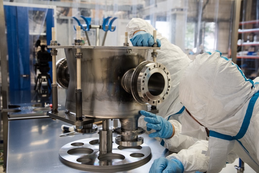
Header Image: Electron Test Stand gun and collector magnet. (Courtesy of Giulio Stancari, Fermilab)

Due to the high stored energy in the HL-LHC beam tails (estimated to be in the order of 34 MJ above 3.5 beam σ with beam emittance of 3.5E-6 rad m [1]), it is desirable to have active halo control providing more margin during all the operational phases of HL-LHC.

Hollow Electron Lenses [2], [3], give a means of depleting the tails without using intercepting material, avoiding the risk of damage and not contributing to machine impedance. Halo particles that migrate into the electric field generated by a hollow electron column travelling concentrically around the circulating proton beam over a short distance, will be ‘kicked’ to larger oscillation amplitudes (a slow, continuous process) and be pushed towards the collimators. This leads to a cleaning of the tails.

At CERN, an option of installing Hollow Electron Lenses [4], [5] for HL-LHC is being studied; one per beam line (~ 40 m left and right from IP4). Each will provide a 5 A ‘tube’ of electrons, confined with a solenoid magnetic field, counter-propagating concentrically around the circulating high energy proton beams over 3 m of interaction length, see Figure 1. In order to accelerate halo depletion, the electron beam can be modulated On/Off at 35 kHz, with 200 ns rise-time, thereby adding a non-linear effect to the kicks given to the halo particles [6]. This way one can switch the e-beam on and off between trains, and target trains at random or a fixed number of turns.

The degree to which the electron and proton beams overlap as well as the electron beam profile will be measured with a new device being developed in collaboration between CERN and Cockcroft Institute [7], [8]. This so-called Beam Gas Curtain (BGC) monitor, is based on imaging beam induced gas fluorescence from a supersonic gas curtain.


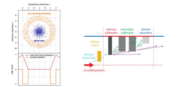
Figure 1: Hollow Electron Beam around the circulated beam (left hand side) and schematics of the Collimation Scheme for HL-LHC (right hand side). (Courtesy of Stefano Redaelli, CERN)

Electron Lens for Space Charge Compensation

Space Charge Compensation of intense ion beams (in SIS18, GSI [9], [10]) by non-neutral plasma columns is being studied within the European ARIES project, a collaboration between GSI (Darmstadt), IAP (Frankfurt), RTU (Riga) and CERN. The Joint Research Activity will develop and build a gun prototype capable of providing electron beams currents of up to 20 A in an oval of 70x50, and able to be modulated with changing transverse and longitudinal profile at a bandwidth of 2 to 5 MHz.

An electron lens test stand is required at CERN for:

  • Acquiring operational experience with electron beams of high intensity and high space charge density (5A in a few mm for the Hollow Electron Lens)
  • Testing components for HL-LHC Hollow Electron Lens (HEL), in particular:
    • characterizing the electron gun current emission yield as a function of cathode temperature (800 to 1000 oC) and extraction voltage (0 to 10kV), and measuring the transverse profile of the electron beam to check uniformity and cathode material quality
    • testing the HV modulator working at 10 kV and 5A, 35 kHz repetition rate
    • testing HV power converters pulsing at 35 kHz
    • designing and testing the HEL control system
    • testing the HEL collector repellers and diagnostics
    • testing the Beam Gas Curtain diagnostics for high-density, hollow electron beams
    • testing the Beam Position Monitor response with the available e-beam modulation
  • Testing components for SIS18 SCC, in particular
    • characterizing the electron gun current emission field and transverse profile of the electron beam
    • testing the HV modulators.

The E-lens Test Stand is being constructed using a staged approach, to commission its main components separately, and validate the measurement techniques.

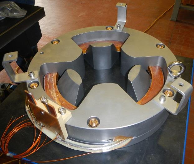
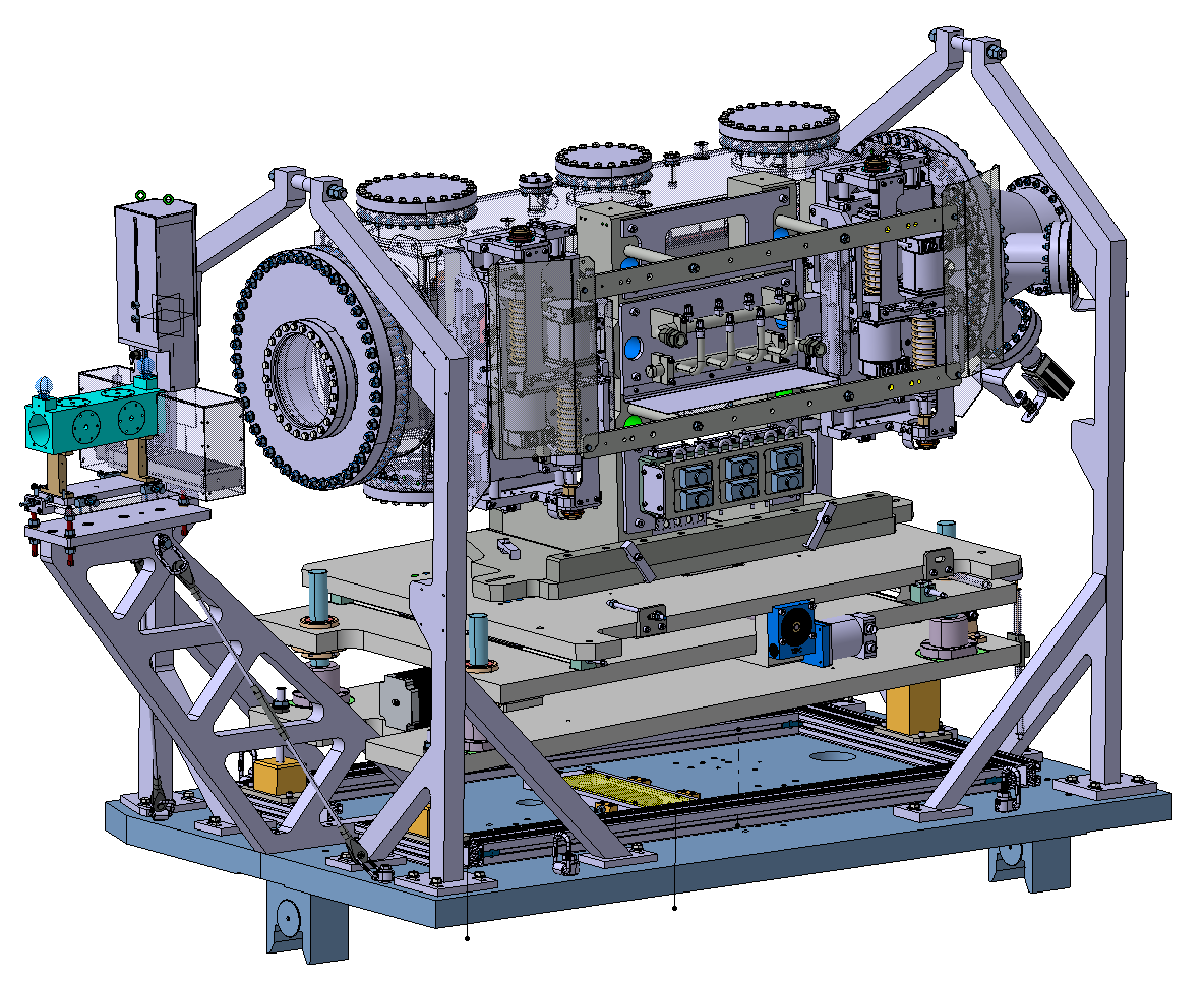
Stage 1 (see Figure 3) is composed of:

  • A gun solenoid of 180 mm aperture, 300 mm length, and up to 0.3T magnetic field
  • A collector solenoid of 135mm aperture, 300 mm length, and up to 0.5T magnetic field
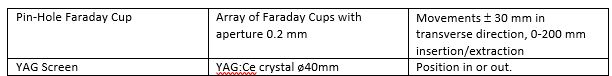
  • A diagnostic box with a Pin Hole Faraday Cup and a YAG screen (see more details later)
  • A bake-out and pumping system to guarantee pressures of the order of 10-10 mbar
  • A collector chamber with passively cooled “Faraday Cup” with viewport.
  • A pulsing device (10 msec 10 Hz, corresponding to a duty cycle of 10-4)
  • Measurement of current with the current transformer in the cathode power converter with 200 MHz bandwidth.

Measurements that can be carried out with Stage 1 are the following:

  • Gun characterization, i.e. measurement of the current emission yield as a function of cathode temperature (typically of the order of 1000 oC) and as a function of the extraction voltage (typically 0 – 10 kV for the HEL gun and up to 25 kV for the SCC gun).
  • Measurements of the beam profile and current with varying magnetic field at the gun.
  • The transverse profile of the electron beam and its energy distribution.
  • Test of auxiliary equipment (e.g. rise time of the anode modulator).

Schematics of the hollow electron gun are shown in Figure 2. 

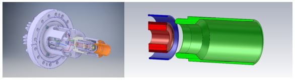
Figure 2. Layout of a hollow electron gun  (as scaled for the from Fermilab design – Tevatron): Left hand side: mechanical assembly (courtesy of D. Perini, CERN). Right hand side: cathode and shaping electrode (in red), control electrode (in blue) and anode (in green). (Image: CERN)

References for this type of gun and the results of similar measurements can be found in [11], [12], [13], [14].

Measurements of the beam profile as a function of the accelerating voltage (at constant extraction voltage), will require an additional power supply (upgrade A). Testing of the HEL HV modulator will need biasing of the collector to reduce the energy dissipated, adding another power supply (upgrade B).

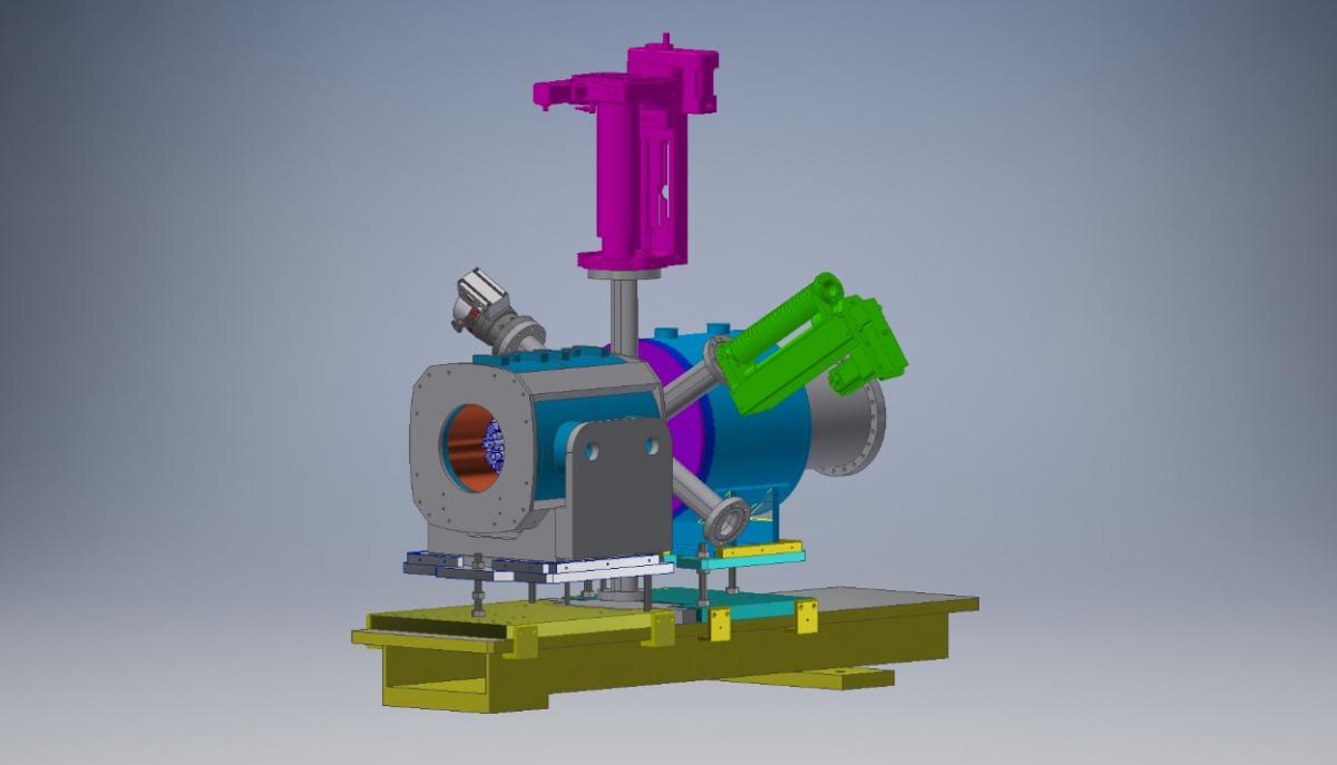
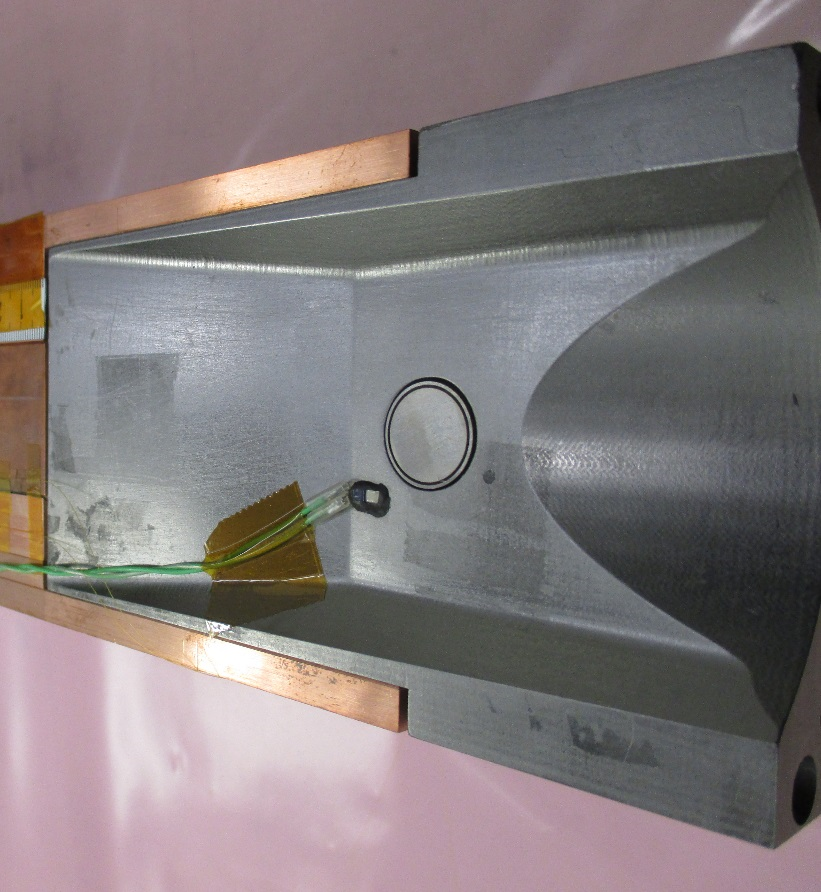
Figure 3. Layout of the Electron Lens Test Stand, Stage 1: composed of a gun and collector solenoid plus a diagnostic box. (Image: CERN)

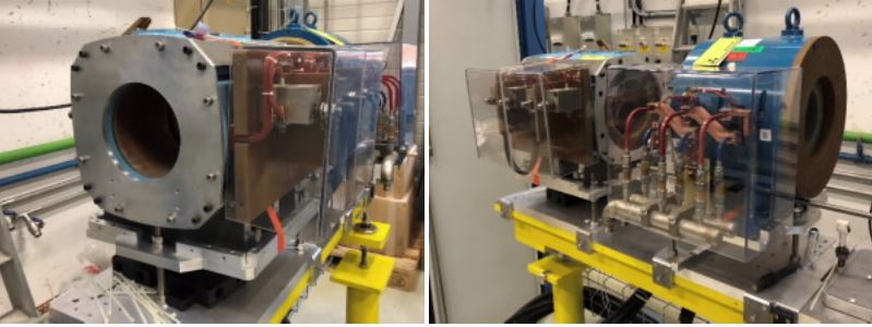
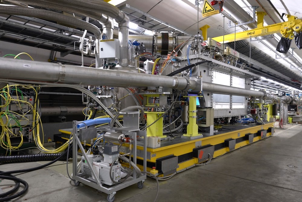
Figure 4. Electron Test Stand gun and collector magnet as from today’s installation. (Image: CERN)

The installation of a drift solenoid (Stage 2, shown in Figure 5) is necessary to study electron beam dynamics, develop the beam position monitor, test the BGC with different electron beam sizes, and full testing of the HV modulator performance (frequency of switching and longitudinal modulation for the ARIES application).

In the current plans, the Stage 2 drift solenoid will be a dry, superconducting solenoid, 1 m long, with a magnetic field up to 4 T. Such a solenoid will allow compression of the electron beam by up to a factor of 3 and greatly increase the span of beam dynamics studies possible.

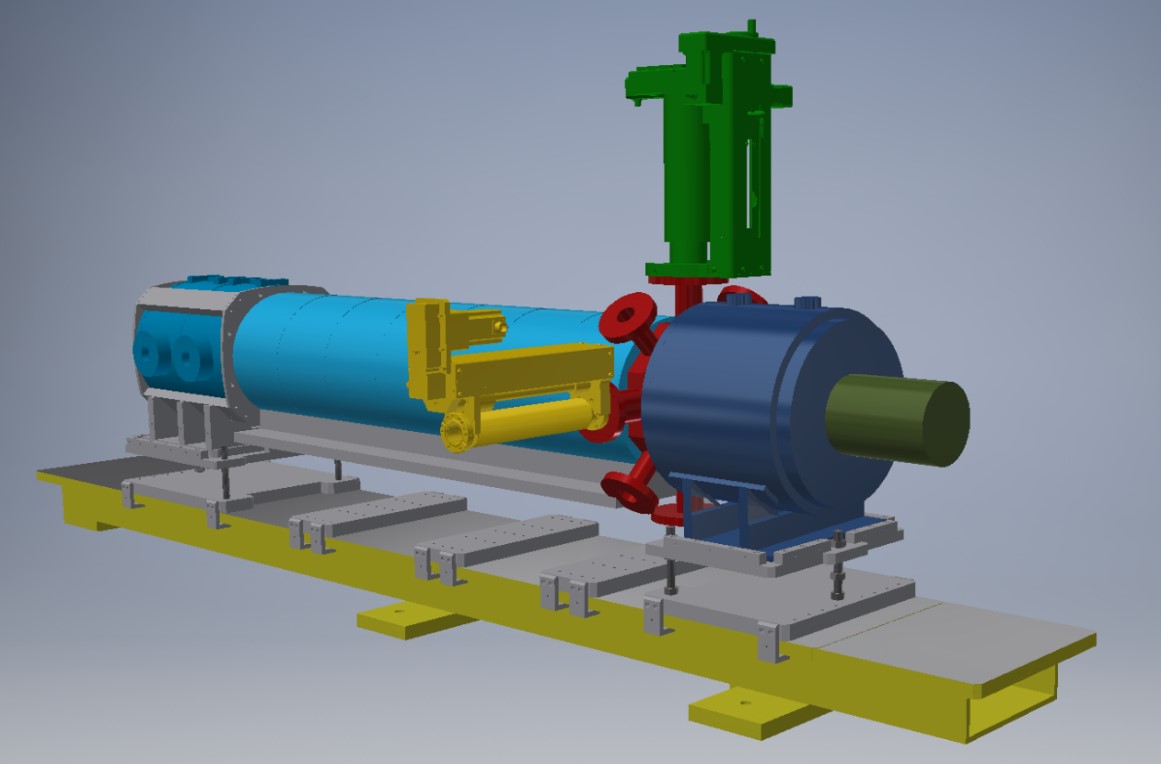
Figure 5. Layout of the Electron Lens Test Stand. Stage 2: derived from Stage 1, adding a drift solenoid between the gun solenoid and the diagnostic box, and upgrading the collector to take more deposited power. (Image: CERN)
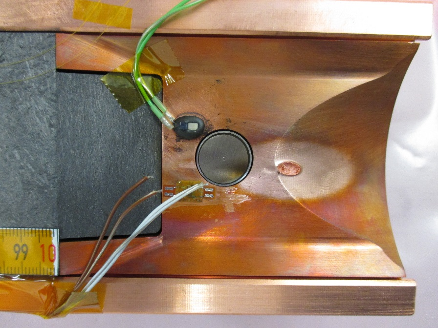
Diagnostic box

The Electron Lens Test Stand diagnostic box (Figure 6) hosts the instrumentation able to measure electron current and transverse profile, namely a Pinhole Faraday Cup and a YAG Screen, and possibly a Langmuir probe to measure the electron temperature, electron density, and electric potential. The diagnostic box vacuum chamber (depicted in Figure 7) has several arms for the insertion of the instrumentation, a turbo-pump and a vacuum gauge. The arms have an hippodrome-like shape to minimize the space between the gun and collector solenoid (so that the magnetic field drop at the box itself is minimal) while guaranteeing that the Pinhole Faraday Cup can be swept laterally to cover the transverse size of the electron beam, and leaving enough conductance for the turbo-pump.

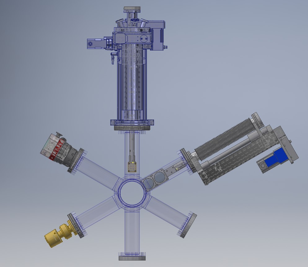
Figure 6. Diagnostic box showing the actuators of the Pinhole Faraday Cup and the YAG Screen, a pump and a vacuum gauge. (Image: CERN)

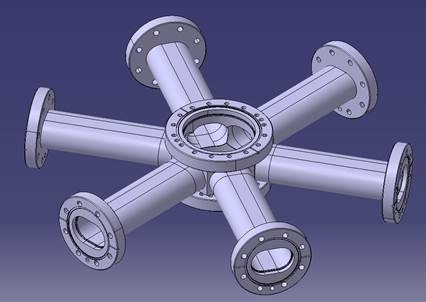
Figure 7. Diagnostic box vacuum chamber. (Image: CERN)

With respect to existing test stands (for example at Fermilab, US, or IAP, Frankfurt), the CERN test stand offers the big advantage of providing diagnostics that sweep through the beam (rather than moving the beam through a fixed diagnostic set-up), a larger accelerating field and a larger drift magnetic field.

The fact of moving the diagnostics rather than the beam will give a more accurate measurement of the transverse beam profile, since the electron beam dynamics for such a non-relativistic beam also depends on the beam position relative to the vacuum chamber walls. For HEL applications, it is very important to accurately establish the shape of the electron beam and its dynamics (i.e. that it stays round along the whole interaction length) since the presence of a residual electric field in the center of the electron beam could perturb the circulating proton beam, especially if pulsed.

The CERN test stand also allows for a comparison between measurements with the Pinhole Faraday Cup, the YAG screen and an eventual beam gas curtain monitor.


References

[1] G. Valentino, presentation at the Review on the needs for a Hollow Electron Lens for the HL-LHC, CERN, 06.10.2016, https://indico.cern.ch/event/567839/contributions/2295258/attachments/1349453/2036619/Halo_MDs_operation_HEL_Review_20161006.pdf
[2] V. Shiltsev, in Proceedings of the CARE-HHH-APD Workshop (BEAM07), CERN-2008-005 (2008) https://care-hhh.web.cern.ch/CARE-HHH/BEAM07/Proceedings/Proceedings/Session%204/S14-Shiltsev-a4.pdf
[3] G. Stancari et al, Phys. Rev. Lett. 107, 084802, https://journals.aps.org/prl/abstract/10.1103/PhysRevLett.107.084802
[4] G. Stancari et al, Conceptual design of hollow electron lenses for beam halo control in the Large Hadron Collider, FERMILAB-TM-2572-APC, CERN-ACC-2014-0248, https://arxiv.org/abs/1405.2033
[5] D. Perini and C. Zanoni, Preliminary Design Study of the Hollow Electron Lens for LHC, CERN-ACC-NOTE-2017-0004  https://cds.cern.ch/record/2242211
[6[ M. Fitterer et al., in Proceedings of IPAC2017, Copenhagen, Denmark, http://accelconf.web.cern.ch/AccelConf/ipac2017/papers/thpab041.pdf
[7] V. Tzoganis, in Proceedings of IPAC2014, Dresden, Germany
[8] H.D. Zhang, in Proceedings of IPAC2017, Copenhagen, Denmark, http://accelconf.web.cern.ch/AccelConf/ipac2017/papers/mopab139.pdf
[9] W.D. Stem at al., in Procedeengs of HB2016, Malmö, Sweden, http://accelconf.web.cern.ch/AccelConf/hb2016/papers/thpm5x01.pdf .
[10] D. Ondreka et al., in Proceedings of IPAC2017, Copenhagen, Denmark, http://accelconf.web.cern.ch/AccelConf/ipac2017/papers/tupva059.pdf
[11] A. Sharapa et al., Nucl. Instrum. Methods Phys. Research A, 406, 169 (1998), https://www.sciencedirect.com/science/article/pii/S0168900297011911?via%3Dihub .
[12] A. Ivanov and M. Tiunov, in Proceedings of the 2002 European Particle Accelerator Conference (EPAC02), Paris, France, June 2002, p. 1634, http://accelconf.web.cern.ch/AccelConf/e02/PAPERS/WEPRI050.pdf .
[13] S. Li and G. Stancari, FERMILAB-TM-2542-APC (August 2012), http://inspirehep.net/record/1181720 .
[14] V. Moens, Masters Thesis, École Polytechnique Fédérale de Lausanne (EPFL), Switzerland, FERMILAB-MASTERS-2013-02 and CERN-THESIS-2013-126 (August 2013) http://cds.cern.ch/record/1599475 .


Panos Charitos, Frank Zimmermann
Unfolding the full potential of a future circular lepton collider
9 Dec 2019

Unfolding the full potential of a future circular lepton collider

A recently proposed acceleration scheme could further increase the performance of a technology-ready circular lepton collider and boost the exploratory potential of the FCC integrated programme.

Volodymyr Rodin (University of Liverpool)
3D mapping of electrostatic fields
11 Jul 2019

3D mapping of electrostatic fields

MEMS sensor successfully used for precise measurement of 3D electrostatic field. A precise field measurement technique such as this offers an interesting opportunity.

Graeme Burt (Lancaster University), Donna Pittaway (STFC), Trevor Hartnett (STFC) and Peter Corlett (STFC)
Daresbury security linac achieves 3.5 MeV
26 Jun 2018

Daresbury security linac achieves 3.5 MeV

Compact aviation cargo scanning linac successfully commissioned at STFC Daresbury Laboratory.

A new JTT shielding adapting ATLAS to Hilumi configuration

Header Image: ATLAS detector (Image: CERN)

For the HL-LHC Collider-Experiment Interface Work Package, their LS3 started last January with the manoeuvres to remove the ATLAS end cup toroid (JTT) shielding.

Why start in LS2 something planned for LS3?

Mainly because the activation of the components in the JTT shielding region will be 25 times higher during LS3 than was during LS1 and so we should try to advance any work that is feasible to reduce future doses to personnel.

The transition between the LHC tunnel and the experimental caverns is the most difficult region in terms of accessibility of the full ring. Currently, there are a number of machine components belonging to the vacuum and beam instrumentation systems located at that precise place, just behind the Target Absorber for Secondaries.  Moving them to the experimental caverns (in the IP side of the TAS) would offer a safer environment for interventions, adding the possibility to operated them remotely and so reduce the workers exposition to radiation.

However, space in the experimental caverns is rare. Every millimetre is  taken when opening of the detectors for routine maintenance tasks . After more than one year of collaborative effort and some compromises, a solution was found to relocate the VAX. In the case of ATLAS, the first of the implications foreseen to host the future VAX being compatible with detector openings was the modification of the JTT shielding.

From the 14th to the 31st January the ATLAS JTT was removed thanks to the ATLAS and CERN Engineering department teams. The transport procedure had to be completely rethink as we did not had any more a not yet completely installed experiment as was the case in 2006. A new support structure and a crab system was installed to allow the removal of the 13 Tones casted iron and boride polyethylene shielding that today is already stored in CERN ISRs waiting for its final treatment.

The new JTT units are today under construction in Pakistan. HMC3, that already contributed to the ATLAS experiment under the supervision of PAEC, should deliver them before the end of LS2. The new pieces have an innovative design compatible with the VAX.

Always having in mind personnel safety, the ATLAS forward shielding blocks will be machined during LS2. This operation requires handling of close to 100T pieces.

From the CMS side work is also frenetic. The new support for the VAX will be already installed during LS2 allowing the relocation of other vacuum equipment, while the forward shielding will also be modified in prevision of the new VAX modules.

The new VAX for ATLAS and CMS is nowadays in its prototyping phase. A new vacuum chamber handling and support compatible with remote operations and the new layout is under construction, and will be thoroughly tested with the collaboration of different CERN groups: Experimental Areas, Vacuum, Transport, Survey and Mechatronics.

Panos Charitos (CERN)
Interview with Mariana Mazzucato: Bridging Research with Innovation
25 Mar 2019

Interview with Mariana Mazzucato: Bridging Research with Innovation

Prof. Mariana Mazzucato on innovation and the concept of "missions".

Daniela Antonio (CERN)
The future of communication and outreach for accelerators
10 Dec 2018

The future of communication and outreach for accelerators

Members from the accelerator communication community gathered at CERN for a workshop.

Outi Heloma (CERN), Isabel Bejar Alonso (CERN)
Education for innovation in Hilumi and FCC
6 Mar 2018

Education for innovation in Hilumi and FCC

What’s in it for innovators in Hilumi and FCC? Twenty young researchers interested in innovation and entrepreneurship participated in this two-day course.

A new step for High-Luminosity LHC

HL-LHC civil engineering works at Point1, Meyrin, Switzerland. (Image: CERN)

Last October took place in Geneva the 8th HL-LHC Collaboration Meeting, the annual gathering of the project community to measure progress and to discuss the latest design and production objectives. A growing community, that has seen during this year the arrival of Triumf (Canada) and IHEP (China) and the increase of contribution from existent collaboration members such as PAEC (Pakistan), Uppsala University (Sweden) or the UK STFC and Universities contributing to HL-LHC.

8thmeeting_HL-LHC.jpg
Members of the collaboration. (Image: CERN)

Plenty of successful milestones were reached in 2018. This year saw the installation of the first crab cavities cryomodules in the SPS, the starting of the civil engineering works and the brilliant results of the fourth short model of the Nb3Sn quadrupole and of the seventh short model of the 11 T. Moreover,the long prototypes of the 11T dipole and the Nb3Sn quadrupole were tested and the first results don’t match those from  the short models, thus demonstrating that the industrialization of magnets is a long path without shortcuts. The 8th annual meeting put together the key actors to analyse what worked and what any deviations from the original plan to ensure that the project is completed on time.

The 8th HL-LHC meeting brought more news for HL-LHC magnets. It gave the opportunity to discuss the advancement of the last tests of the second D1 model produced in KEK in Japan and the development of the corrector magnets at CERN and in Spain (CIEMAT), Italy (INFN) and China (IHEP), with several prototypes already tested.

Furthermore, there were many/ lessons learnt from the installation in the SPS of the test bench housing the DQW (double-quarter wave) crab cavities cryomodule. The construction of the associated infrastructure showed that the objective was reached only because all operations were studied and planned in detail. Without precise planning and a fully devoted team we wouldn’t meet the tight schedule. The cryomodule has showed an  excellent behaviour and all data obtained has been discussed and will be used to improve the design of the LHC cavities.

There was also the occasion to discuss on the first results of the magnesium diboride superconducting link demonstrator (Demo 1) that contains the first 20 kA wires cabled in industry. Meanwhile, as this article is written. Demo 1 has been powered, though in a non-final configuration,with excellent croiygenic and electrical performance confirming the choice illustrated in  the annual meeting that  was focused  to discuss the redesign of the Distribution feedboxes another key element of the cold powering.

The gathering was also the occasion to evaluate if new systems have to be added to the baseline. When discussing on the evolution of the LHC bean dumping system, (LBDS) it was decided the need of a technical review as today looks like a real need. Other options such as the electron lenses of the crystal collimation presented their latest results but will continue to be pursued with the expectation to find the necessary external funding as in-kind contribution

Several decisions were also presented such as the revamping of the existing cryogenic system that  allows to avoid a new cryoplant in point 4 or the optimization of the matching sections and the new remote alignment system that will induce savings in the project while increasing avaibility in operation and reducing the dose to personnel.

There was also time to discuss the advancement of the warm powering and the latest news from the cold diodes that have shown to survive the the  radiation test with HiLumi dose and the results on the shielded beam screen or the LS2 plans for the TANB and the shielding round the experiments.

Finally during a public visit, the HL-LHC collaborators sawthe progress on the civil engineering works, where in that moment the excavations had reached 30 metres at Point 1 and 25 metres at Point 5. The two 80-metre shafts should be fully excavated by the beginning of 2019.

Four days, some 180 presentations to push the technologies developed for the High-Luminosity LHC and beyond.

Achintya Rao (CERN)
Proton Synchrotron prepared for higher injection energies
26 Mar 2020

Proton Synchrotron prepared for higher injection energies

CERN’s oldest working accelerator has a new injection kicker magnet and will soon receive a new septum as well.

Mike Barnes (CERN)
First workshop on Pulse Power for Kicker Systems held at CERN
28 Jun 2018

First workshop on Pulse Power for Kicker Systems held at CERN

The PULPOKS 2018 workshop brought more than 40 participants to discuss the latest developments in the field of pulsed power for particle accelerators

Ricardo Torres (University of Liverpool)
The Tale of Two Tunnels
10 Dec 2018

The Tale of Two Tunnels

Liverpool will be turned into a particle accelerator exhibition.

A new generation of beam screens

When HL-LHC was approved, the vacuum team faced a huge challenge, to create a new generation of beam screens. The LHC has already a beam screen that is already quite unique in its kind, but HL required far more strict characteristics. From one side, tungsten absorbers are integrated to intercept collisions debris leading to  heat load requirements of a factor 50 higher compared with the one for LHC and for another they have much larger aperture, optimized for beam optics, inducing huge Lorentz forces during a magnet quench of around 33 tons per meter per quadrant. A breakthrough was needed.

The shielded beam screen is  a complex octagonal shaped assembly made out of a co-laminated and perforated copper and stainless steel sheet. It is equipped with tungsten blocks laid on the tube and kept in place by means of elastic rings and pins, cooling tubes and thermal links. The design is based on a thermal decoupling between the internal beam screen tube and the absorbers to keep the temperature in a thermodynamically efficient range and on a flexible assembly to ensure the transfer of the Lorentz forces induced in the absorbers to the cold bore tube. To develop the new beam screens, the team had to consider not just the 2D modelling but a full 3D modelling as the beam screen was shielded by tungsten blocks equipped with local copper thermal links.

They also had to use advanced simulation techniques considering all the factors such as the combined thermal and electromechanical behaviour. Several aspects had to be studied in detail as the transfer of heat between the beam screens and the absorber blocks in Tungsten, the cooling circuits or the thermal transfer with the cold bore. "Thermal aspects are extremely challenging points," says Cedric Garion, responsible of the beam screen design, as in this case we are working at 60-80 K and not as for the LHC at the range of 4-20 K.

Since two years the CERN vacuum group has done a systematic campaign to validate its innovative design starting with an 80 cm model to the present 2m long prototype. This campaign has not been easy as during the 6th Annual meeting in 2016 a new requirement was added: the magnet protection scheme was complemented with a novel Coupling-Loss Induced Quench (CLIQ) system which became part of the baseline in addition to the standard quench heaters. From one day to another the new beam screen had to be able to withstand a new type of oscillatory load induced by CLIQ and work in a completely different mechanical regime.

The team reviewed in few months the consequences for the design and reworked the holding systems and the geometry of the Tungsten blocks. In a record time they were ready to test the new prototype able to resist to the new configuration with the new quench protection system.

"This summer was a really exciting moment," says Marco Morrone, one of the engineers involved in the design and in charge of the tests, as we submitted the new beam screen to extreme conditions. In fact, the prototype of the Q1 beam screen was cool down to 1.9k and subjected to currents beyond the ultimate current. The beam screen prototypes withstand magnet quenches and the results obtained were compared with the models giving a perfect fit between the simulations and what was observed.

On the other hand, thermal tests of a beam screen prototype have been carried out and have shown excellent thermal performance of this complex assembly.  A very good decoupling is observed between the absorbers and the beam screen tube, whose temperature is perfectly defined by the helium temperature. In addition, a low heat leak, below 0.5 W/m, has been measured from the massive shielded beam screen to the 1.9 K cold bore tube. These outstanding results are in very good agreement with the estimations obtained by simulations.

To obtain such good results the vacuum group had to innovate in a lot of aspects. For example, the springs on the holding system are done in additive printing. Another real challenge has been the design of the thermal links that at the same time transfer heat, warranty flexibility will resist to extreme forces. Finally the tungsten blocks are just hold to transfer forces to the cold bore. Definitively the beam screen has become a new technological jewel of HL-LHC.

Panagiotis Charitos (CERN)
Interview with Robert-Jan Smits
8 Oct 2018

Interview with Robert-Jan Smits

A sit down with Robert-Jan Smits one of the architects of the European research area and a firm supporter of scientific knowledge and technology as means to address today’s greatest challenges.

Chris Edmonds (University of Liverpool)
Tactile Collider
13 Mar 2018

Tactile Collider

Sensory exploration of LHC science for children with visual impairment

Panos Charitos
Groundbreaking for the HL-LHC civil engineering work
26 Jun 2018

Groundbreaking for the HL-LHC civil engineering work

Civil works have begun on the ATLAS and CMS sites to build new underground structures for the High-Luminosity LHC.

Power tests of HL-LHC quadrupole

Fig. 1:

In July, the fourth short model of the Nb3Sn quadrupole for the HL-LHC interaction regions was tested in SM18. This is the first magnet with the final Bruker-OST Restacked Rod Process (RRP®) conductor, with 108/127 layout, which shall be used for eight out of ten magnets of this series. As the third model tested one year ago, this was fully manufactured and assembled in CERN’s laboratory 927.

The magnet reached nominal current (7 TeV operation) with one quench, and ultimate current (7.5 TeV operation) after five quenches. “It has been the fastest training of the short models tested so far, approaching the performance of HQ, the magnet developed in the 2000’s by LARP that is the father of MQXF” – says J. Carlos Perez, in charge of the 927 magnet laboratory. The most relevant parameter for operation is the training after thermal cycle, since it provides an indication of the magnet behavior after installation. For this model no quench was required to reach 7.5 TeV operation, proving a perfect memory of the training.

Fig.2:

Magnetic measurements confirmed a low value of the first order harmonics, already observed in the US prototype and in the third short model. This dodecapole component is 0.05% of the main field, whereas it should be not larger than 0.01%. A fine-tuning, foreseen in the initial design shall be carried out to recenter this unwanted harmonic around zero.  This will be done through a modification of shims around the coil by a mere 0.125 mm.

The coils of the fifth and last short model have been manufactured, and the magnet, named MQXSF6, will be assembled in autumn. These coils are made with the final Bruker-EAS Powder-In-Tube (PIT) conductor, which will be used for one prototype and for two series magnet. “The MQXFS6 magnet will complete the short model programme of the HL-LHC Nb3Sn quadrupoles” – says G. de Rijk, in charge of the MSC/MDT section leading the short models and the correctors of HL-LHC – “but we remain ready to continue further work on short models, should we need additional information to be fed in the full size magnets”. The construction of the first full size CERN prototype MQXFBP1 is ongoing, and the second US prototype MQXFAP2 is undergoing cool-down for a test to start in a few weeks in BNL.

Leah Hesla (Fermilab)
Fermilab achieves 14.5-tesla field for accelerator magnet, setting new world record
15 Jul 2020

Fermilab achieves 14.5-tesla field for accelerator magnet, setting new world record

Fermilab achieved a 14.5-tesla field strength for an accelerator steering dipole magnet, surpassing their previous record of 14.1 T.

Romain Muller (CERN)
And the winners of the ARIES Proof-of-Concept fund are…
3 Jul 2018

And the winners of the ARIES Proof-of-Concept fund are…

Take a closer look at the potential of the selected projects

Graeme Burt (Lancaster University), Donna Pittaway (STFC), Trevor Hartnett (STFC) and Peter Corlett (STFC)
Daresbury security linac achieves 3.5 MeV
26 Jun 2018

Daresbury security linac achieves 3.5 MeV

Compact aviation cargo scanning linac successfully commissioned at STFC Daresbury Laboratory.

A big step towards the superconducting magnets of the future

Last April, the FRESCA2 dipole magnet reached a field of 14.6T. This field value sets a new world record for dipole magnets with a free aperture, and breaks the old record established in 2008 of 13.8T by LBNL with the HD2 dipole magnet.

The development of magnets with fields beyond 10T started in Europe in 2004 with the FP6-CARE-NED project where the basic technologies were developed and specifically the Nb3Sn conductor which is the workhorse for the HL-LHC 11 T magnet, the LHC luminosity upgrade programme and baseline option for the more powerful 16T magnets for the Future Circular Collider study.

“FRESCA2 has already played an important role in the development of the new magnets for the High Luminosity LHC and will soon help develop the next generation of magnets." says Gijs de Rijk, head of the FRESCA2 programme.

The FRESCA2 dipole magnet design and construction was started in the framework of the FP7-EuCARD-HFM project in 2009 and has been co-financed by HL-LHC. The FRESCA2 magnet is much larger than a LHC magnet, measuring 1.5 m in length and 1 m in diameter. This allows the magnet to have a large aperture, measuring 10 centimetres, so that it can house the cables being tested, as well the sensors to monitor their behaviour. 

The FRESCA2 magnet before the start of the tests. (Image: Maximilien Brice/CERN). 

The magnet is the outcome of a successful collaborative effort between CERN and CEA-Saclay. The technology developments for FRESCA2 were essential for the new Nb3Sn magnets of HL-LHC. Formed by the superconducting niobium-tin compound and cooled to 1.9 kelvin (-271°C), it had already reached a field of 13.3 teslas in August 2017. Then, with a modification of the mechanical pre-stressing, it started a new series of tests in April before reaching its record intensity.

FRESCA2 will also be used to test coils formed from high-temperature superconductors. The goal is to test not only the maximum electrical current but also study in depth the effects of so high magnetic fields and the behaviour of the coil. Results from these measurements feed current efforts to design high-field magnets for future energy-frontier colliders. 

The magnet was tested to the nominal operating field, and achieved 13.3T in August 2017 after a very rapid training of 5 quenches. As a second step, the mechanical preload was increased and the magnet was retested in April 2018 to explore the ultimate operating limit. In this configuration FRESCA2 reached a maximum bore field of 14.6T at a temperature of 1.9K with additional 6 training quenches. The tests are currently being performed in the new purposely built test cryostat of the SM18 cryogenic test station at CERN.

This result is a major milestone in the progression towards high field accelerator magnets beyond HL-LHC. The future of FRESCA2 is to provide background fields for tests of cables and small coils, a new facility that will provide unique test capabilities.

Ch. Bracco, D. Carbajo Perez and A. Perillo Marcone
Ensuring safer operation at higher luminosities
12 Mar 2018

Ensuring safer operation at higher luminosities

The higher bunch intensities and smaller beam emittances expected in HL-LHC call for a novel design of the Target Dump Injection (TDI)

Panagiotis Charitos (CERN)
EASIschool '18: A summer to remember
8 Oct 2018

EASIschool '18: A summer to remember

A unique learning experience for the participants of the first school organized by EASITrain, this summer in Vienna.

Panagiotis Charitos
EASISchool Grenoble
3 Dec 2019

EASISchool Grenoble

Cryogenics and its applications took central stage during the EASISchool 2 that was held from the 30th of September to the 4th of October in two CEA sites, Paris-Saclay and Grenoble, France.

Groundbreaking for the HL-LHC civil engineering work

The groundbreaking ceremony for the launch of the civil engineering works took place on Friday 15 June 2018 with the presence of the CERN management, the French and Swiss Authorities and the CERN Council.

"The High-Luminosity LHC will extend the LHC's reach beyond its initial mission, bringing new opportunities for discovery, measuring the properties of particles such as the Higgs boson with greater precision and exploring the fundamental constituents of the universe ever more profoundly," mentioned CERN's Director-General Fabiola Gianotti during the ceremony.

The increase in the number of collisions in HL-LHC, means more observations of rare phenomena and more chances for discovery. As an example, the upgrade will increase the number of Higgs bosons that can be produced by the LHC from 1.2 million to 15 million.  The HL-LHC data will enable the improvement of the precision on Higgs boson couplings by a factor of 2 to 3 with respect to the previous LHC running. 

Two contracts for the civil engineering works have been adjudicated in March 2018 to a consortium MARTI TUNNELBAU, MARTI ÖSTERREICH and MARTI DEUTSCHLAND for the Point 1 works and to IMPLENIA SCHWEIZ, BARESEL and IMPLENIA CONSTRUCTION consortium for Point 5. At each point, the work consist of the construction of an access shaft, a service cavern and underground galleries as well as five new surface buildings. The site mobilization has started on both Points. The shaft excavations will start end of June 2018 and will be completed before the end of the year.

The excavations will be performed with electrical road-headers to minimize the vibration level on the LHC machine and its detectors, which will be in operation with beams during this period. In parallel, the two consultants are progressing in the detailed design of underground structures. The underground excavation works will be completed by mid 2020 during the next long shut-down and the works, including surface buildings, will be completed by Autumn 2022.

The effect of the first Civil Engineering work on the site surface on the proton losses in the LHC. One can clearly recognize the 22Hz perturbation of the excavation equipment

After completion of this major upgrade, the LHC is expected to produce data in high-luminosity mode from 2026 onwards. By pushing the frontiers of accelerator and detector technology, it will also pave the way for future higher-energy accelerators. “Audacity underpins the history of CERN and the High-Luminosity LHC writes a new chapter, building a bridge to the future,” said CERN’s Director for Accelerators and Technology, Frédérick Bordry. “It will allow new research and with its new innovative technologies, it is also a window to the accelerators of the future and to new applications for society.


Yiota Foka (CERN)
Master Class captivates the next generation of scientists
11 Jul 2019

Master Class captivates the next generation of scientists

CERN, DKFZ Heidelberg and GSI Darmstadt engage the next generation of scientists through a hands-on experience on particle therapy.

Daniela Antonio (CERN)
Power converters specially designed for CERN can now be used by the wider accelerator community
11 Dec 2019

Power converters specially designed for CERN can now be used by the wider accelerator community

CERN has developed new software layers to allow the wider particle accelerator community to use the CERN-specific power converters controls.

Stéphanie Vandergooten
Apply now to the Joint Universities Accelerator School
23 Sep 2019

Apply now to the Joint Universities Accelerator School

Interested to learn more about Particle Accelerators? Apply now to the 2020 JUAS School in Archamps to follow 5-week courses on particle accelerators.

World’s first crabbing of a proton beam

The first test of superconducting crab cavities to rotate a beam of protons was performed on 23 May using a beam from CERN’s Super Proton Synchrotron (SPS) accelerator. These cavities are a key component of the High-Luminosity Large Hadron Collider (HL-LHC). A total of 16 such cavities will be installed in the HL-LHC – eight near ATLAS and eight near CMS.

Figure 1: DQW Crab Cavity Prototype being assembled at CERN.

In the LHC and HL-LHC, the two counter-rotating bunches collide at an angle at each collision point of the experiments. When installed at each side of the ATLAS and CMS experiments, the crab cavities will “tilt” bunches of protons in each beam to maximise their overlap at the collision point thus increasing the luminosity. The crab cavities are expected to increase the overall luminosity by 15 to 20% and improve the quality of data collected by the experiments. Crab cavities were already used in the KEKB collider in Japan for electrons and positrons, but never with protons, which are more massive and at significantly higher energies.

Figure 2: The Crab Cavity Cryostat installed on a movable table in the CERN SPS.

The first crab cavity prototypes were manufactured at CERN in 2017 in collaboration with STFC and USLARP. The cavities were assembled in a cryostat and tested at CERN-SM18 facility prior to its installation into the SPS. The cavities were installed in the SPS accelerator during the last winter technical stop for machine development studies in the SPS.

Figure 3: Images a bunch in the CERN SPS for 2 different voltage settings in the Crab Cavities. Left without voltage and deflection. Right with 1MV voltage and deflection.


The first beam tests were performed on 23 May at 4.5 K with a single proton bunch accelerated to 26 GeV and with a bunch intensity of 0.2-1×10¹¹ p/b. The crab cavities were powered to about 10% of their nominal voltage in the first tests and later increased to up to 50% limited mainly due to vacuum rise. The “crabbing” was observed using head-tail monitor with large enough bandwidth and resolution to observe the intra-bunch orbit induced by the crab cavities. These tests mark the start-up of a unique facility for testing superconducting cavities on a high-current, high-energy proton beam. The results mark an important milestone to prove the feasibility of using such cavities with long proton bunches for increasing the luminosity in the HL-LHC.

In the coming months, the cavities will be commissioned to their nominal temperature of 2K and slowly ramp the kick voltage to their nominal voltage of 3.4 MV. During the rest of the year, the cavities will undergo a series of tests to fully validate their operation for a robust operation in the HL-LHC era.  

Panos Charitos (CERN)
ISOLDE's new solenoid spectrometer
21 Mar 2019

ISOLDE's new solenoid spectrometer

Novel experiments to study the evolution of nuclear structure, exotic nuclear shapes and the formation of elements made possible with ISOLDE's new solenoid spectrometer.

Sabrina El yacoubi
How to access free of charge state-of-the-art accelerator testing facilities across Europe?
Mike Barnes (CERN)
First workshop on Pulse Power for Kicker Systems held at CERN
28 Jun 2018

First workshop on Pulse Power for Kicker Systems held at CERN

The PULPOKS 2018 workshop brought more than 40 participants to discuss the latest developments in the field of pulsed power for particle accelerators

Ensuring safer operation at higher luminosities

The TDI (Target Dump Injection) is a beam-intercepting device installed on the two injection lines of the LHC (Large Hadron Collider) to protect the superconducting elements of the machine during injection in case of a malfunction of the injection kickers.

Due to the higher bunch intensities and smaller beam emittances expected in the HiLumi-LHC phase, and following the operational experiences of the TDI, a complete revision of the design has been performed. The result of this reengineering work is the TDIS (Target Dump Injection Segmented),a key element for the safe operation of LHC at high luminosity.   

The major changes that can improve the reliability of this component are:  

  • A more efficient cooling circuit better integrated in the jaw, in order to dissipate the beam induced Radio Frequency (RF) heating.
  • A more robust and reliable motorization system and fixation points to contain and guide any possible deformation.
  • A new geometry with smaller cavities, better contacts and RF fingers to damp as much as possible the HOM.

Several other aspects were taken in consideration while reengineering the TDIS and as the letter “s” indicates, the new design is segmented! The new modular design will simplify the assembly procedure, the installation, the maintenance and will improve the robustness, setup accuracy and operational reliability of the system.

The new injection dump consists of three modules, independently movable, of equal length (each ~1.6 m long) hosting different absorber materials: two modules with low-Z absorbers blocks (graphite R4550) and one with a sandwich of higher-Z materials (Ti6Al4V and CuCr1Zr). A careful choice of the material ensures that no damage occurs in the machine as well as that the TDIS will cope with all direct beam impact conditions. Impedance, e-cloud and radiological aspects were also taken into account in the final design.

After several years of engineering and specification work, the efforts now move to the procurement of materials and components for the assembly of the TDIS prototype. As of today, most of the components required to build-up one TDIS prototype (plus one module for validation purposes at CERN’s HiRadMat testing facilities) are in the manufacturing phase, although some key elements have already been produced. Amongst them, the absorbing blocks and one back-stiffener of a jaw to be installed in the HiRadMat module. This stiffener is a structural component intended to ensure the requested flatness of the jaw’s surface exposed to the beam and is produced out of TZM (Molybdenum alloy) in order to withstand the high thermomechanical loads induced in case of beam impact.

3D view of the HiRadMat module that will be assembled in 2018 along with a full TDIS prototype (Image credit: Luca Gentini). 

Finally, it should be noted that the aforementioned manufactured parts are currently going through the qualification process at CERN. Ultrasonic inspection and metrology analysis are so far completed and the next stage is vacuum testing to confirm the compatibility of the graphite blocks and the TZM back-stiffener with an ultra-high vacuum environment.

The start date for the assembly process of the prototype and the HiRadMat module is planned for early June, right after the arrival of the vacuum vessels.

Maurizio Vretenar (CERN)
Bringing particle accelerators on ships
16 Jul 2019

Bringing particle accelerators on ships

The first test to use a particle accelerator to clean the exhaust gases of a ship took place in Riga in July 2019. The first results are encouraging.

Panagiotis Charitos
EASISchool Grenoble
3 Dec 2019

EASISchool Grenoble

Cryogenics and its applications took central stage during the EASISchool 2 that was held from the 30th of September to the 4th of October in two CEA sites, Paris-Saclay and Grenoble, France.

Stéphanie Vandergooten
Apply now to the Joint Universities Accelerator School
23 Sep 2019

Apply now to the Joint Universities Accelerator School

Interested to learn more about Particle Accelerators? Apply now to the 2020 JUAS School in Archamps to follow 5-week courses on particle accelerators.

A new step towards successful MgB2 superconducting coils

On 7th March the INFN-LASA laboratory completed the construction and successfully tested a superconducting coil in MgB2 (Magnesium di-Boride based conductor) to be used in a high order corrector magnet. Development of MgB2 coils for a Round Coil Superferric Magnet corrector was launched in the framework of the HL-LHC project IR magnets. This design, proposed in the 70s by Russian scientists, allows to create any multipole with the same round coil through a three dimensional shaping of the iron; the low curvature radius of the coil allows using MgB2 superconductor. 

Application of this design to the HL-LHC high order correctors started in 2014 by our late lamented Giovanni Volpini with CERN support. Computations showed that this option had a lower efficiency in terms of longitudinal space, and therefore the classical superferric option with Nb-Ti and standard two dimensional iron shaping was retained; INFN-LASA built three correctors based on this design in the past two years, and two more types are being built in collaboration with industry. Nonetheless, the MgB2 RCSM prototype magnet has remained in the development line to explore the manufacturing aspects of this design, and to have a MgB2 corrector available for high energy accelerators, a prima for this technology.

A single coil, wound with conductor produced by Columbus Superconductors (Genova), was tested in LASA without the iron yoke; this coil is the active part of the RCSM magnet, which will be assembled and tested in September 2019. The coil, cooled at 4.2 K with liquid helium, reached without any training quench the specification current (“ultimate current”, 160 A), passing also the stability test of one hour at the ultimate current. The coil was then energized to larger currents to investigate the limiting current, which resulted in 243 A; this is 73% of the intersection of the load line with the critical current for virgin, not-degraded, conductor. It should be noted that this current limit was reached without intermediate quench (no training).


Image Credit: INFN/LASA

“The test result is beyond our expectations,” says Massimo Sorbi from INFN-LASA. “MgB2 virgin conductors are very prone to degradation when they are wound and manipulated with even better procedures used for the other common superconductor magnets based on NbTi. Our cryogenic test was also complemented with the measurement of the thermal contraction of coil (literature is lacking of this data regarding MgB2 coils), which will enable a better design of the mechanical structure for the final magnet.” “This is a relevant technological spin-off of the HL LHC project”, says Ezio Todesco, in charge of HL-LHC IR magnets, “enabled by the synergy between INFN-LASA and CERN”.


Image Credit: INFN/LASA

Joseph Piergrossi (European XFEL)
New solutions for challenges among complementary light sources
8 Oct 2018

New solutions for challenges among complementary light sources

EUCALL developed strategies for laser-based and accelerator-based sources of UV/X-ray light.

Joseph Wolfenden (University of Liverpool)
Synchrotron radiation imaging at 200 miles
15 Jul 2020

Synchrotron radiation imaging at 200 miles

Experts from the University of Liverpool and Diamond Light Source have taken a step further and conducted a series of remote access beam measurements.

Marco Zanetti (INFN & Univ. Padua), Frank Zimmermann (CERN)
Workshop shines Light on Photon-Beam Interactions
7 Dec 2017

Workshop shines Light on Photon-Beam Interactions

The ARIES Photon Beams 2017 Workshop was held in Padua, Italy in late November 2017.