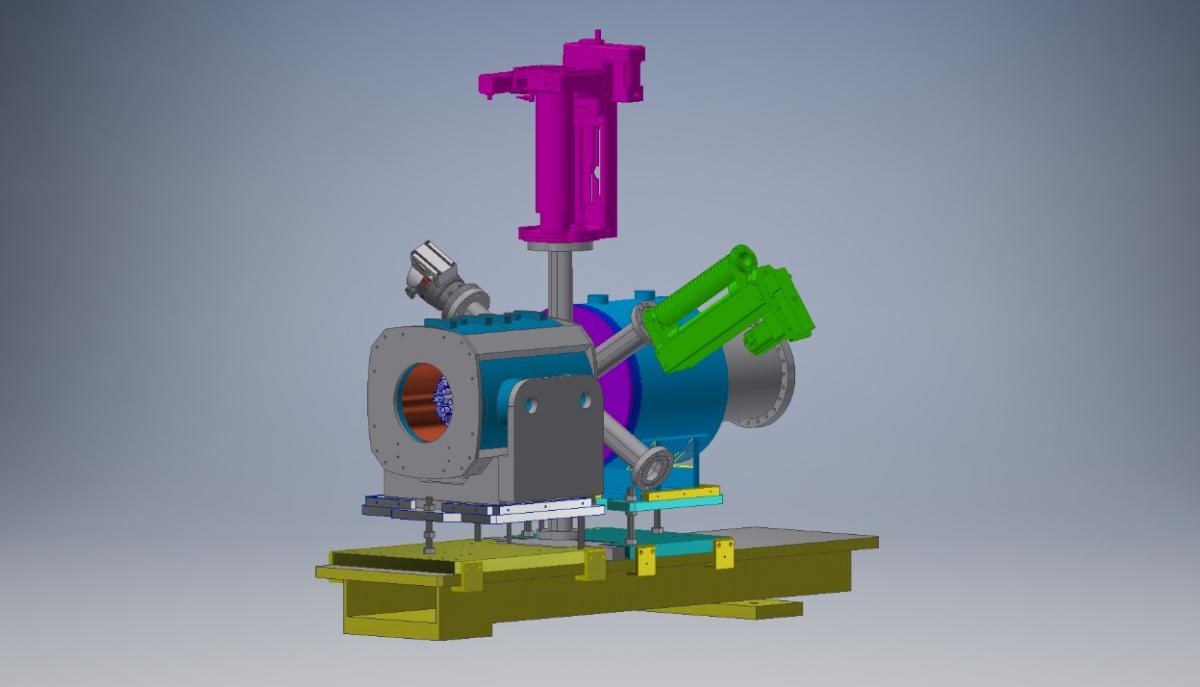
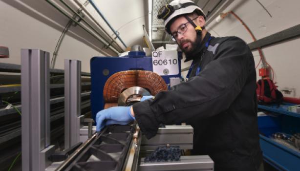
Header Image: Electron Test Stand gun and collector magnet. (Courtesy of Giulio Stancari, Fermilab)
Due to the high stored energy in the HL-LHC beam tails (estimated to be in the order of 34 MJ above 3.5 beam σ with beam emittance of 3.5E-6 rad m [1]), it is desirable to have active halo control providing more margin during all the operational phases of HL-LHC.
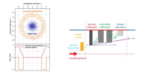
Hollow Electron Lenses [2], [3], give a means of depleting the tails without using intercepting material, avoiding the risk of damage and not contributing to machine impedance. Halo particles that migrate into the electric field generated by a hollow electron column travelling concentrically around the circulating proton beam over a short distance, will be ‘kicked’ to larger oscillation amplitudes (a slow, continuous process) and be pushed towards the collimators. This leads to a cleaning of the tails.
At CERN, an option of installing Hollow Electron Lenses [4], [5] for HL-LHC is being studied; one per beam line (~ 40 m left and right from IP4). Each will provide a 5 A ‘tube’ of electrons, confined with a solenoid magnetic field, counter-propagating concentrically around the circulating high energy proton beams over 3 m of interaction length, see Figure 1. In order to accelerate halo depletion, the electron beam can be modulated On/Off at 35 kHz, with 200 ns rise-time, thereby adding a non-linear effect to the kicks given to the halo particles [6]. This way one can switch the e-beam on and off between trains, and target trains at random or a fixed number of turns.
The degree to which the electron and proton beams overlap as well as the electron beam profile will be measured with a new device being developed in collaboration between CERN and Cockcroft Institute [7], [8]. This so-called Beam Gas Curtain (BGC) monitor, is based on imaging beam induced gas fluorescence from a supersonic gas curtain.
Figure 1: Hollow Electron Beam around the circulated beam (left hand side) and schematics of the Collimation Scheme for HL-LHC (right hand side). (Courtesy of Stefano Redaelli, CERN)
Electron Lens for Space Charge Compensation
Space Charge Compensation of intense ion beams (in SIS18, GSI [9], [10]) by non-neutral plasma columns is being studied within the European ARIES project, a collaboration between GSI (Darmstadt), IAP (Frankfurt), RTU (Riga) and CERN. The Joint Research Activity will develop and build a gun prototype capable of providing electron beams currents of up to 20 A in an oval of 70x50, and able to be modulated with changing transverse and longitudinal profile at a bandwidth of 2 to 5 MHz.
An electron lens test stand is required at CERN for:
- Acquiring operational experience with electron beams of high intensity and high space charge density (5A in a few mm for the Hollow Electron Lens)
- Testing components for HL-LHC Hollow Electron Lens (HEL), in particular:
- characterizing the electron gun current emission yield as a function of cathode temperature (800 to 1000 oC) and extraction voltage (0 to 10kV), and measuring the transverse profile of the electron beam to check uniformity and cathode material quality
- testing the HV modulator working at 10 kV and 5A, 35 kHz repetition rate
- testing HV power converters pulsing at 35 kHz
- designing and testing the HEL control system
- testing the HEL collector repellers and diagnostics
- testing the Beam Gas Curtain diagnostics for high-density, hollow electron beams
- testing the Beam Position Monitor response with the available e-beam modulation
- Testing components for SIS18 SCC, in particular
- characterizing the electron gun current emission field and transverse profile of the electron beam
- testing the HV modulators.
The E-lens Test Stand is being constructed using a staged approach, to commission its main components separately, and validate the measurement techniques.
Stage 1 (see Figure 3) is composed of:
- A gun solenoid of 180 mm aperture, 300 mm length, and up to 0.3T magnetic field
- A collector solenoid of 135mm aperture, 300 mm length, and up to 0.5T magnetic field
- A diagnostic box with a Pin Hole Faraday Cup and a YAG screen (see more details later)
- A bake-out and pumping system to guarantee pressures of the order of 10-10 mbar
- A collector chamber with passively cooled “Faraday Cup” with viewport.
- A pulsing device (10 msec 10 Hz, corresponding to a duty cycle of 10-4)
- Measurement of current with the current transformer in the cathode power converter with 200 MHz bandwidth.
Measurements that can be carried out with Stage 1 are the following:
- Gun characterization, i.e. measurement of the current emission yield as a function of cathode temperature (typically of the order of 1000 oC) and as a function of the extraction voltage (typically 0 – 10 kV for the HEL gun and up to 25 kV for the SCC gun).
- Measurements of the beam profile and current with varying magnetic field at the gun.
- The transverse profile of the electron beam and its energy distribution.
- Test of auxiliary equipment (e.g. rise time of the anode modulator).
Schematics of the hollow electron gun are shown in Figure 2.
Figure 2. Layout of a hollow electron gun (as scaled for the from Fermilab design – Tevatron): Left hand side: mechanical assembly (courtesy of D. Perini, CERN). Right hand side: cathode and shaping electrode (in red), control electrode (in blue) and anode (in green). (Image: CERN)
References for this type of gun and the results of similar measurements can be found in [11], [12], [13], [14].
Measurements of the beam profile as a function of the accelerating voltage (at constant extraction voltage), will require an additional power supply (upgrade A). Testing of the HEL HV modulator will need biasing of the collector to reduce the energy dissipated, adding another power supply (upgrade B).
Figure 3. Layout of the Electron Lens Test Stand, Stage 1: composed of a gun and collector solenoid plus a diagnostic box. (Image: CERN)
Figure 4. Electron Test Stand gun and collector magnet as from today’s installation. (Image: CERN)
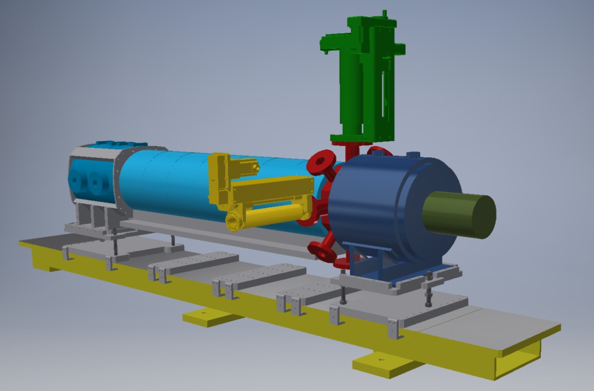
The installation of a drift solenoid (Stage 2, shown in Figure 5) is necessary to study electron beam dynamics, develop the beam position monitor, test the BGC with different electron beam sizes, and full testing of the HV modulator performance (frequency of switching and longitudinal modulation for the ARIES application).
In the current plans, the Stage 2 drift solenoid will be a dry, superconducting solenoid, 1 m long, with a magnetic field up to 4 T. Such a solenoid will allow compression of the electron beam by up to a factor of 3 and greatly increase the span of beam dynamics studies possible.
Figure 5. Layout of the Electron Lens Test Stand. Stage 2: derived from Stage 1, adding a drift solenoid between the gun solenoid and the diagnostic box, and upgrading the collector to take more deposited power. (Image: CERN)
Diagnostic box
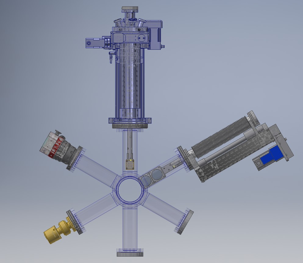
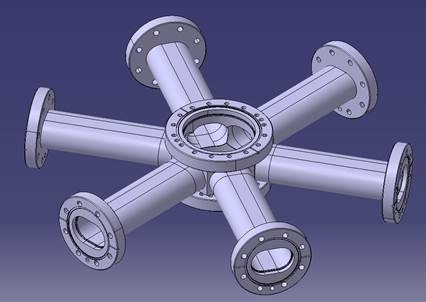
The Electron Lens Test Stand diagnostic box (Figure 6) hosts the instrumentation able to measure electron current and transverse profile, namely a Pinhole Faraday Cup and a YAG Screen, and possibly a Langmuir probe to measure the electron temperature, electron density, and electric potential. The diagnostic box vacuum chamber (depicted in Figure 7) has several arms for the insertion of the instrumentation, a turbo-pump and a vacuum gauge. The arms have an hippodrome-like shape to minimize the space between the gun and collector solenoid (so that the magnetic field drop at the box itself is minimal) while guaranteeing that the Pinhole Faraday Cup can be swept laterally to cover the transverse size of the electron beam, and leaving enough conductance for the turbo-pump.
Figure 6. Diagnostic box showing the actuators of the Pinhole Faraday Cup and the YAG Screen, a pump and a vacuum gauge. (Image: CERN)
Figure 7. Diagnostic box vacuum chamber. (Image: CERN)
With respect to existing test stands (for example at Fermilab, US, or IAP, Frankfurt), the CERN test stand offers the big advantage of providing diagnostics that sweep through the beam (rather than moving the beam through a fixed diagnostic set-up), a larger accelerating field and a larger drift magnetic field.
The fact of moving the diagnostics rather than the beam will give a more accurate measurement of the transverse beam profile, since the electron beam dynamics for such a non-relativistic beam also depends on the beam position relative to the vacuum chamber walls. For HEL applications, it is very important to accurately establish the shape of the electron beam and its dynamics (i.e. that it stays round along the whole interaction length) since the presence of a residual electric field in the center of the electron beam could perturb the circulating proton beam, especially if pulsed.
The CERN test stand also allows for a comparison between measurements with the Pinhole Faraday Cup, the YAG screen and an eventual beam gas curtain monitor.
References
[1] G. Valentino, presentation at the Review on the needs for a Hollow Electron Lens for the HL-LHC, CERN, 06.10.2016, https://indico.cern.ch/event/567839/contributions/2295258/attachments/1349453/2036619/Halo_MDs_operation_HEL_Review_20161006.pdf
[2] V. Shiltsev, in Proceedings of the CARE-HHH-APD Workshop (BEAM07), CERN-2008-005 (2008) https://care-hhh.web.cern.ch/CARE-HHH/BEAM07/Proceedings/Proceedings/Session%204/S14-Shiltsev-a4.pdf
[3] G. Stancari et al, Phys. Rev. Lett. 107, 084802, https://journals.aps.org/prl/abstract/10.1103/PhysRevLett.107.084802
[4] G. Stancari et al, Conceptual design of hollow electron lenses for beam halo control in the Large Hadron Collider, FERMILAB-TM-2572-APC, CERN-ACC-2014-0248, https://arxiv.org/abs/1405.2033
[5] D. Perini and C. Zanoni, Preliminary Design Study of the Hollow Electron Lens for LHC, CERN-ACC-NOTE-2017-0004 https://cds.cern.ch/record/2242211
[6[ M. Fitterer et al., in Proceedings of IPAC2017, Copenhagen, Denmark, http://accelconf.web.cern.ch/AccelConf/ipac2017/papers/thpab041.pdf
[7] V. Tzoganis, in Proceedings of IPAC2014, Dresden, Germany
[8] H.D. Zhang, in Proceedings of IPAC2017, Copenhagen, Denmark, http://accelconf.web.cern.ch/AccelConf/ipac2017/papers/mopab139.pdf
[9] W.D. Stem at al., in Procedeengs of HB2016, Malmö, Sweden, http://accelconf.web.cern.ch/AccelConf/hb2016/papers/thpm5x01.pdf .
[10] D. Ondreka et al., in Proceedings of IPAC2017, Copenhagen, Denmark, http://accelconf.web.cern.ch/AccelConf/ipac2017/papers/tupva059.pdf
[11] A. Sharapa et al., Nucl. Instrum. Methods Phys. Research A, 406, 169 (1998), https://www.sciencedirect.com/science/article/pii/S0168900297011911?via%3Dihub .
[12] A. Ivanov and M. Tiunov, in Proceedings of the 2002 European Particle Accelerator Conference (EPAC02), Paris, France, June 2002, p. 1634, http://accelconf.web.cern.ch/AccelConf/e02/PAPERS/WEPRI050.pdf .
[13] S. Li and G. Stancari, FERMILAB-TM-2542-APC (August 2012), http://inspirehep.net/record/1181720 .
[14] V. Moens, Masters Thesis, École Polytechnique Fédérale de Lausanne (EPFL), Switzerland, FERMILAB-MASTERS-2013-02 and CERN-THESIS-2013-126 (August 2013) http://cds.cern.ch/record/1599475 .
